Design & Engineering

  • Home
  • Design & Engineering
video popup bg image

Design & Engineering

The main framing of PEB systems is analyzed by the stiffness matrix method. The design is based on allowable stress design (ASD) as per the American institute of Steel Construction specification or the IS 800.The design program provides an economic and efficient design of the main frames and allows the user to utilize the program in different modes to produce the frame design geometry, loading and the desired load combinations as specified by the building code opted by the user. The program operates through the maximum number of cycles specified to arrive at an acceptable design. The program uses the stiffness matrix method to arrive at an acceptable design. The program uses the stiffness matrix method to arrive at the solution of displacements and forces. The strain energy method is adopted to calculate the fixed end moments, stiffness and carry over factors. Numerical integration is used.

Design Cycle

The design cycle consists of the following steps:

  • Set up section sizes and brace locations based on the geometry and loading specified for the frame design.
  • Calculate moment, shear, and axial force at each analysis point for each load combination.
  • Compute allowable shear, allowable axial and allowable bending stress in compression and tension at each analysis point.
  • Compute the corresponding stress ratios for shear, axial and bending based on the actual and allowable stresses and calculate the combined stress ratios.
  • Design the optimum splice location and check to see whether the predicted sizes confirm to manufacturing constraints.
  • Using the web optimization mode, arrive at the optimum web depths for the next cycle and update the member data file.
  • At the end of all design cycles, an analysis is run to achieve flange brace optimization.
video popup bg image

Frame Loading

Frame design can handle different types of loadings as described below:

  • All the building dead loads due to sheeting, purlins, etc. and the self weight of the frame.
  • Imposed live load on the frame with tributary reductions as well.
  • Collateral load such as false ceiling, light fixtures, AC ducting loads, sprinkler systems and many other suspended loads of similar nature.
  • Wind loads input such as basic wind speed or basic wind pressure that will be converted to deign wind pressure as per the building code specified by the user and shall be applied to the different members of the building according to the coefficients mentioned in the codes prescribed by the user.
  • The standard building codes like MBMA, UBC, ANSI, IS:875 part 3 etc are used fro this purpose.
  • Crane and non crane loading can be specified by the user and the program has the capability to handle these special loads and combine them with the other loads as required.
  • Seismic loads corresponding to the different zone categories of various international codes can also be defined and combined with other load cases as required.
  • Temperature loads can also be specified in the form of different differential temperature value on centigrade and specifying the appropriate coefficient for the thermal expansion.
  • Load combinations with appropriate load factors can be specified by the user as desired.

Design Codes

Following are the main design codes generally used:

  • AISC: American institute of steel construction manual
  • AISI: American iron and steel institute specifications
  • MBMA: Metal building manufacturer’s code
  • ANS: American national standards institute specifications
  • ASCE: American society of civil engineers
  • UBC: Uniform building code
  • IS: Indian standards
video popup bg image

Design Criteria

Following are the main design criteria generally used:

  • DESIGN METHOD :Allowable stress design method is used as per the AISC specifications.
  • DEFLECTIONS : Unless otherwise specified, the deflections will go to MBMA, AISC criteria and standard industry practices.
  • PRIMARY FRAMING : Moment resisting frames with pinned or fixed bases.
  • SECONDARY FRAMING : Cold formed Z sections or C sections for purlins or girts designed as continuous beams spanning over rafters and columns with laps.
  • LONGITUDANAL STABILITY : Wind load on building end walls is transferred through roof purlins to braced bays and carried to the foundations through diagonal bracing.
  • DESIGN SOFTWARE :The latest software that is used for design is Auto Cad, Tekla, Pro E, Solid Works.
  • DESIGN PROCESS : The frame data is assembled based on number of frame members, number of joints, number of degrees of freedom, the conditions of restraint and the elastic properties of the members. Based on this, the data is stored and member section properties are computed. The overall joint stiffness matrix is obtained based on the above frame data by summation of individual stiffness matrices considering all possible displacements. The load vector is then generated based on the loading data and the unknown displacements are obtained by inverting the overall joint stiffness matrix and multiplying with the load vector.

Have A Project For Us?

081411 50264
Construction Projects

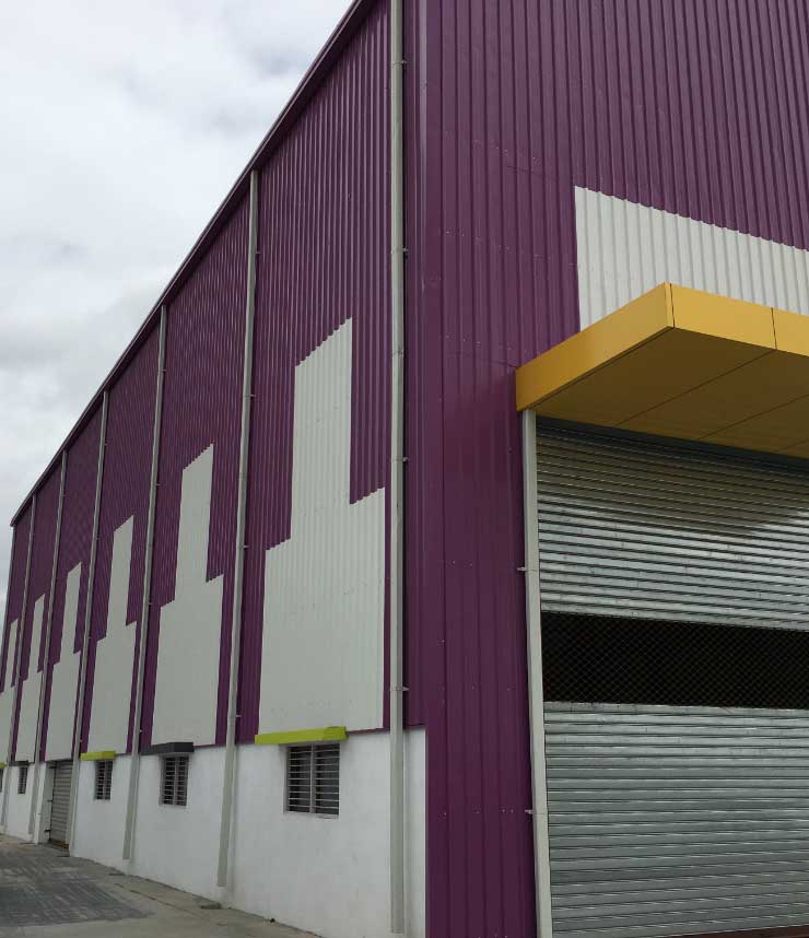
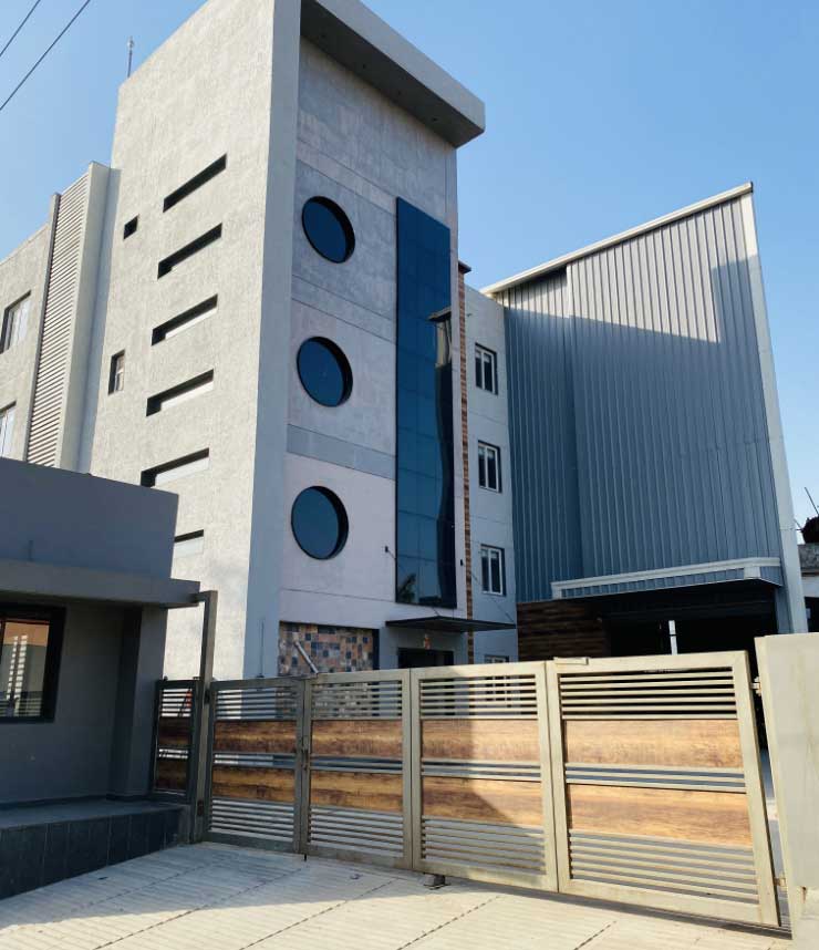
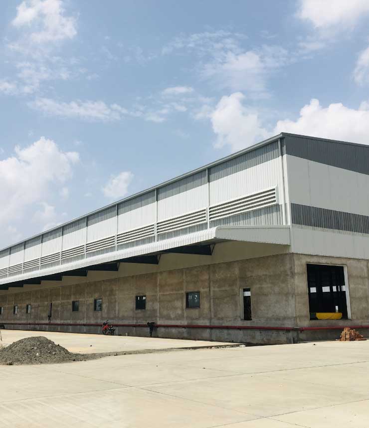
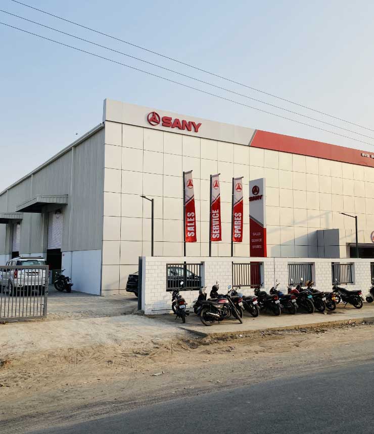
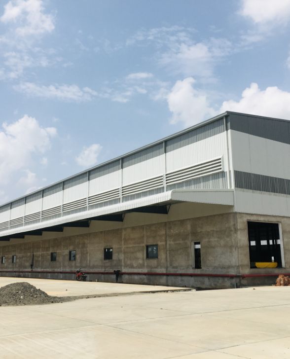
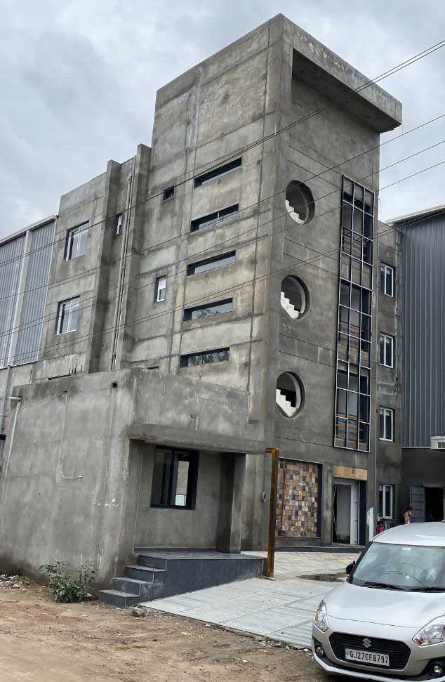
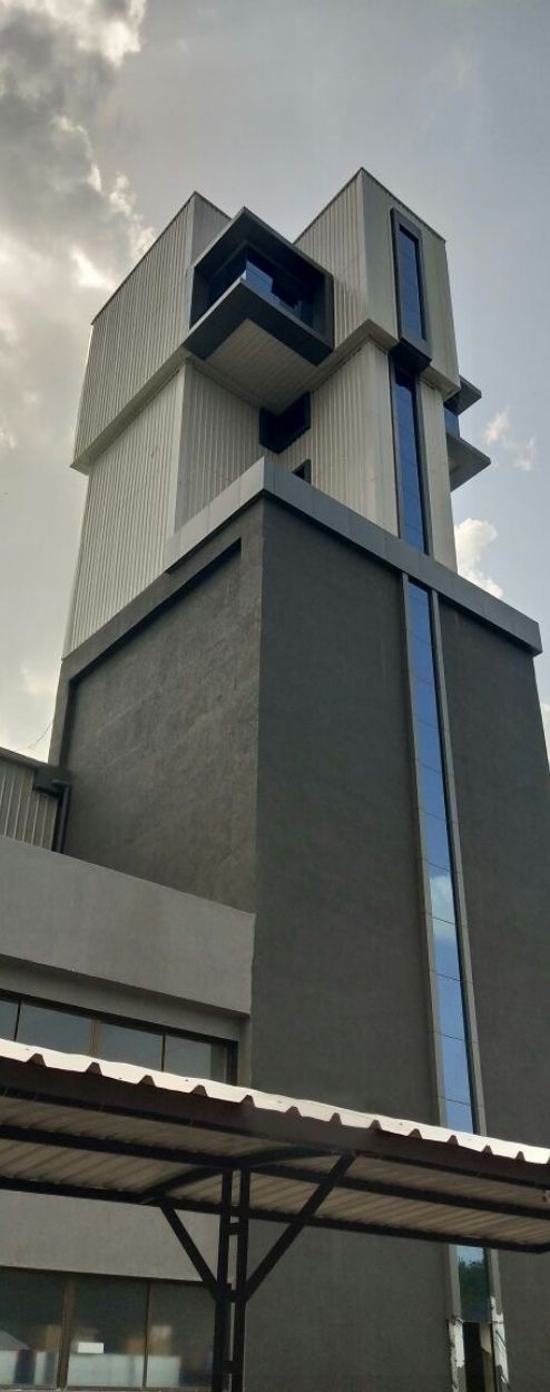
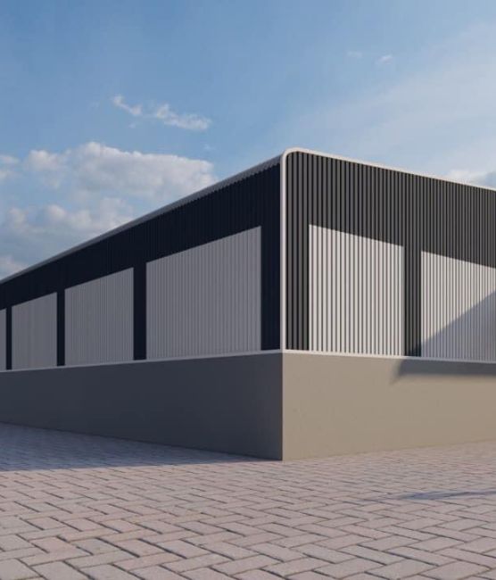
Our Completed Projects